Design Nodeflow
Perform the following steps to design a Nodeflow.
- Browse the categories and select a node.
- Drag this node and drop it to the canvas. For example, "Add Callback" node is dragged in the canvas. It will be the first node after "Start".
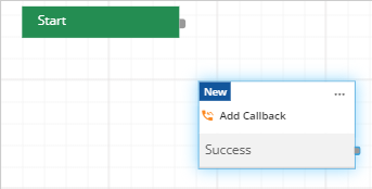
Figure: Adding a Node
The user can again drag-and-drop the same node to the Canvas Area. However, the other copy of the same node will be named differently.
- The node shows the events. The nodes that are meant to stop the execution will be directed to "Default Stop" by default.
- Click "..." icon at the right corner of a node to open the Node Menu, which contains the following options.

Figure: Node Menu
It contains the following options.- Show More: Click it to show all events.
- Delete: Click it to delete the node.
Case 1 (Deleting Single Node): It shows the following message.
Figure: Warning before deleting a Node
Case 2 (Deleting Single Node that has transitions): If the node has transitions to other nodes, the following message is displayed while trying to delete it.
Figure: Warning before deleting a Node that has transitions
Case 3 (Deleting Multiple Nodes):The user can select multiple nodes clicking each node after pressing "CTRL" node. Now, press "DEL" key on the keyboard. It shows the following warning message.
Figure: Warning before deleting Multiple Nodes
You can click "more" button to view the name of the hidden node in the above pop-up.
If the nodes (selected for deletion) are a part of a Nodeflow, the overall functionality of the Nodeflow might break. Also, the deleted nodes cannot be restored.
Click "Delete" to delete the selected nodes. The user can also press "DEL" key.
- Drag more nodes to the canvas.
- At the canvas, scroll down continuously to zoom in and scroll up to zoom out.
- Click anywhere in the canvas (at the blank area) and move the mouse to any direction to move through the canvas.
- Click the end point of "Start" node and bring the arrow to the node with which Nodeflow will start.
- Click the end point of the node to see the two lines, which lets the Administrator decide the transition of the Nodeflow.
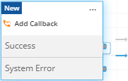
Figure: Transition Options
It contains the following two types of transition lines.- Unconditional Transition: Select the grey line for the unconditional transition. Unconditional Transition is simple. Once an event of a node is generated, the event of another node will start executing. The process will stop at "Default Stop" node.
- Conditional Transition: Select the blue line for a conditional transition. If the administrator is connecting an event of a node to the event of another node with a blue directed line, the condition is displayed in the targeted event in its Node Configuration.
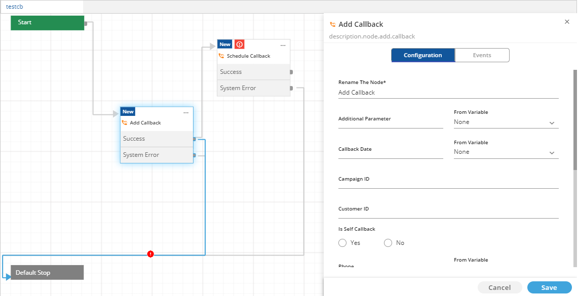
Figure: Conditional Transition
Specify the condition in a JavaScript Code. Click to open the inbuilt JavaScript Editor to write the code.
Click "Save". Now, the transition will happen only when the condition specified in the JavaScript code is satisfied.
- Connect one node to another using these transitions. Click anywhere between the lines to create a break point and then redirect it to another node.
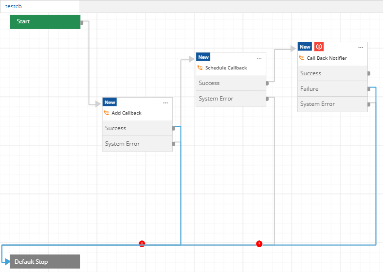
Figure: Sample Nodeflow
There are two arrows in transition from "Add Callback" and "Schedule Callback" nodes. Use the middle arrow to add another node here.There can be multiple transition arrow-based lines from one node. Press and hold "CTRL+SHIFT" keys and do a left click of the pointing device (touchpad or mouse) on a transition to select it. Once selected, press "DEL" key to delete it.
- Validations and Errors: An error icon
 is displayed in the node if
- any mandatory attribute is missing.
- there is no "In-Transition" except the Start Node.
- there is no "Out-Transition" except the Default-Stop Node.
- there is a syntax error in Prescript or PostScript codes.
-
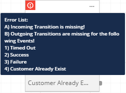
Figure: Error Message List
- the node does not have any transition for an event.
- there is a syntax error in the Conditional Transition.
- the name or condition is not specified in the Conditional Transition. Any error related to an element on the interface is also listed on the interface in the red color.
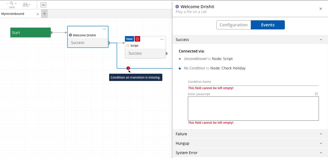
Figure: Validation error related to Conditional Transition of the node
- Click a node header, and it will show its properties on the right side of the canvas.
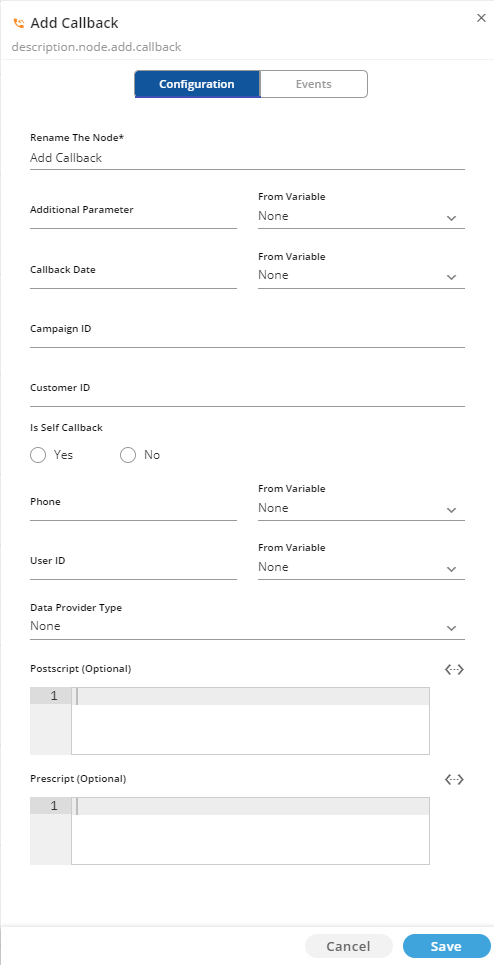
Figure: Node Properties
It contains the following two tabs.- Configuration: This tab allows the user to configure the attributes, select the variables, and provide the custom JavaScript code that can run before and after the execution of the node.
Make any change in the configuration and click "Save". - Events: This tab contains the list of events available in this node.
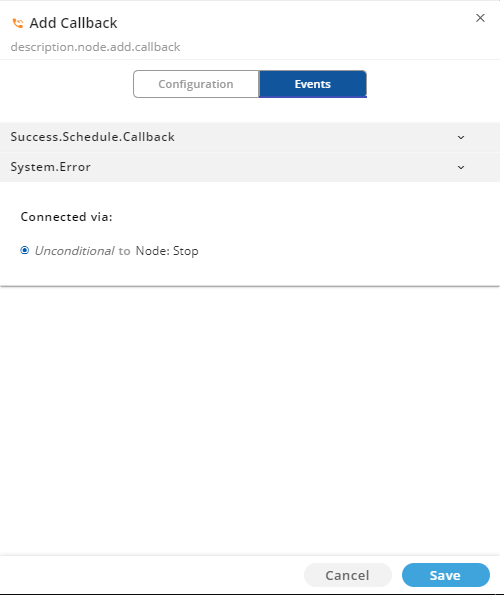
Figure: Events
Click any event to see to which node it is linked and using which transition (conditional or unconditional). -
Following is a screenshot of sample Nodeflow.

Figure: Sample Nodeflow
Go to "File" Menu and click "Export" to save the Nodeflow.
-
Undo and Redo Actions: The user can now undo (reverse the last action) and redo (reversing the last Undo operation) in Ameyo Synthesizer. The user can press CTRL+Z to undo the last actions, whereas, use CTRL+Y or SHIFT+CTRL+Z key combinations can be used to redo the action that has been undone.
25 States of the following actions can be undone or redone.- Placement of nodes in the Canvas
- Deletion of any element
- Saved Node Configuration Changes: These changes are made in Node Configuration that has been saved by clicking "Save" button.
- Saved Node Events Changes: These changes are made in Events of Nodes that have been saved by clicking "Save" button.
- Saved Transition Conditions: These Transition Conditions have been saved by clicking "Save" button.
- Saved Script Changes: These changes are made in the Prescript and Postscript fields that have been saved by clicking "Save" button.
Similarly, the last 25 Undo Operations can be redone.
- Configuration: This tab allows the user to configure the attributes, select the variables, and provide the custom JavaScript code that can run before and after the execution of the node.
In this document, we have discussed the configuration of "Add Callback Node". The Configuration of all nodes is quite similar as the General Configuration discussed here and Configuration of "Add Callback Node". Know more...
Modal to help the User Experience for Quick Designing of Nodeflow
If the number of nodes is more than expected (for example, 30), then the nodes will be scattered over the large area in Synthesizer known as "canvas". It would not be possible for the user to visualize all nodes at once and connect them easily using the transition lines.
To solve this issue, "Connect to" modal has been introduced in Ameyo Application Server. When the user drags a transition from a node and drop it on the canvas, then "Connect to" modal is displayed.
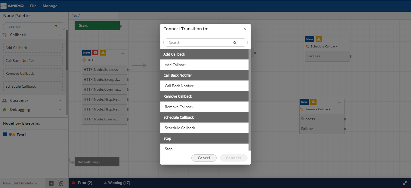
Figure: "Connect to" Modal
The User can select the target node to which the selected node has to be connected.
Reusable Conditions
If a condition has to be used in a different node, the Administrator has to perform the manual steps for doing the same. To make it easy, Ameyo introduced the reusability of conditions. Now, a Condition can be saved and reused anywhere in the Nodeflow like a Variable.
Reusable Conditions
In "Manage" menu, a new option, "Condition" has been added. Click this command to access "Condition" modal where the Administrator can create and manage the conditions.
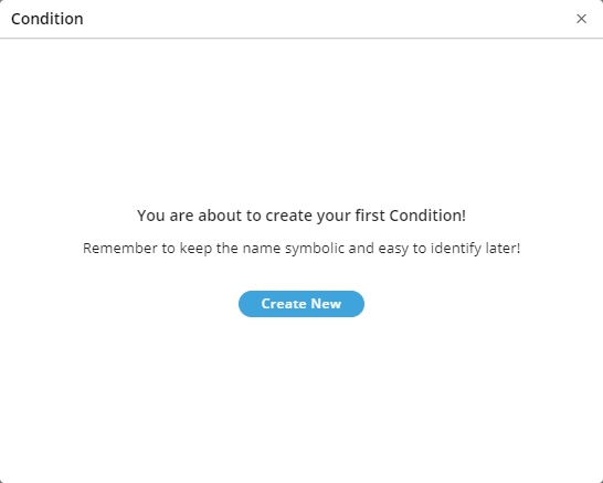
Figure: Condition Modal
If no condition is created, then it shows the message, "You are about to create your first Condition!".
The Administrator can click "Create New" to create a new condition. It shows the following modal.
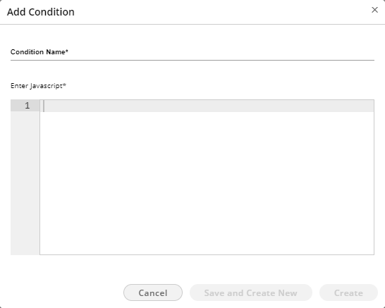
Figure: Create New Condition
Provide a name for the condition and add the JavaScript Code.
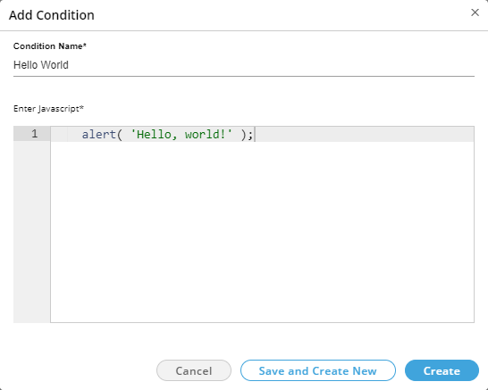
Figure: Sample Condition
Click "Create New" button to create the node, whereas the Administrator can click "Save and Create New" to save this node and proceed to create another new condition.
After creating the nodes, "Condition" modal displays the created nodes.
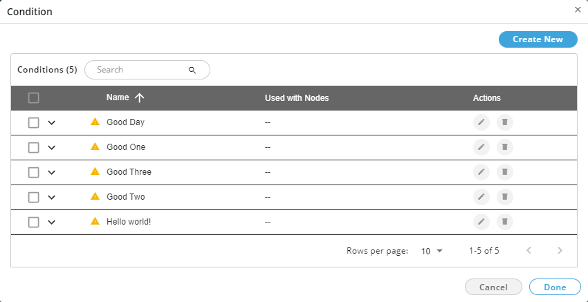
Figure: List of Conditions
Here, the user can perform the following actions.
View the Details of Condition: The User can expand a condition to view the list of nodes where this condition is being used.
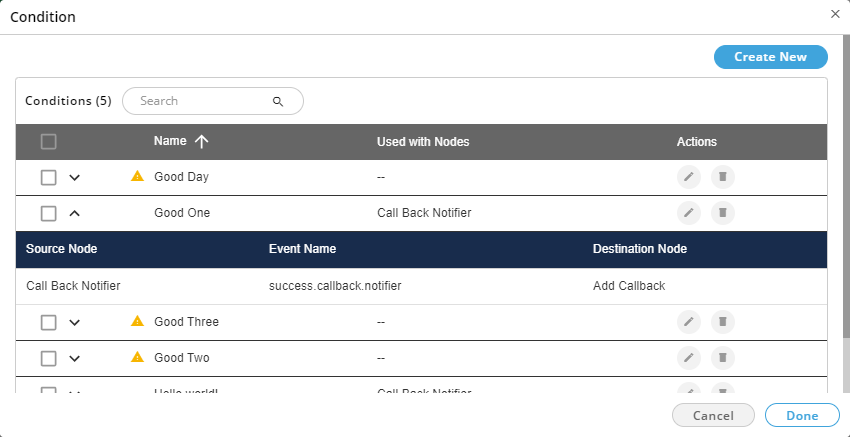
Figure: Details of a Condition
If the condition is not being used in any node, then
 icon is displayed with that condition. When the User expands such a node, then a message is displayed.
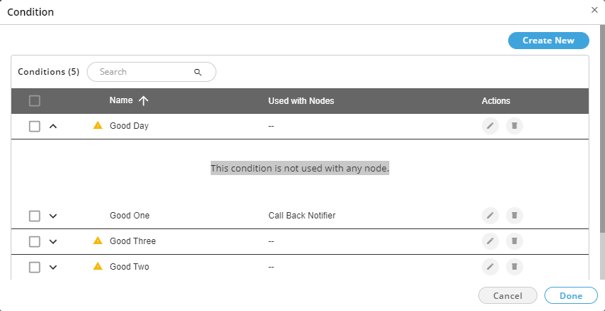
Figure: Condition is not being used.
Name on Transition: The name of conditions is also displayed on the Transitions.
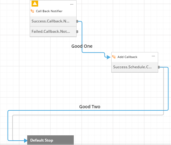
Figure: Conditions are being displayed on Transitions.
Pagination: The User can select the number of conditions to be displayed on a page and navigate between the pages.
Edit the Condition: Click
 icon to edit the condition using the following modal.
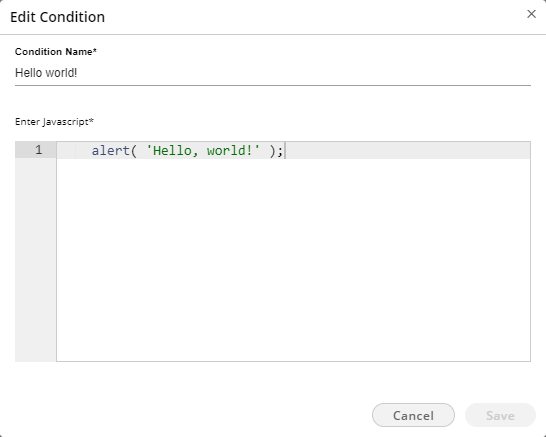
Figure: Edit a Condition
The User can edit the name and code. If the condition is being used with the transitions, then the following confirmation message is displayed.

Figure: Message to confirm the modification of a condition
Delete the Condition: Click
 icon to delete the condition. It shows the following warning message before deleting the condition.
Figure: Warning before deleting a Condition
Click "Delete" to delete the condition.
Bulk Operation: The User can click the checkbox in the header to select all conditions of a page collectively. The User can also select multiple conditions manually.
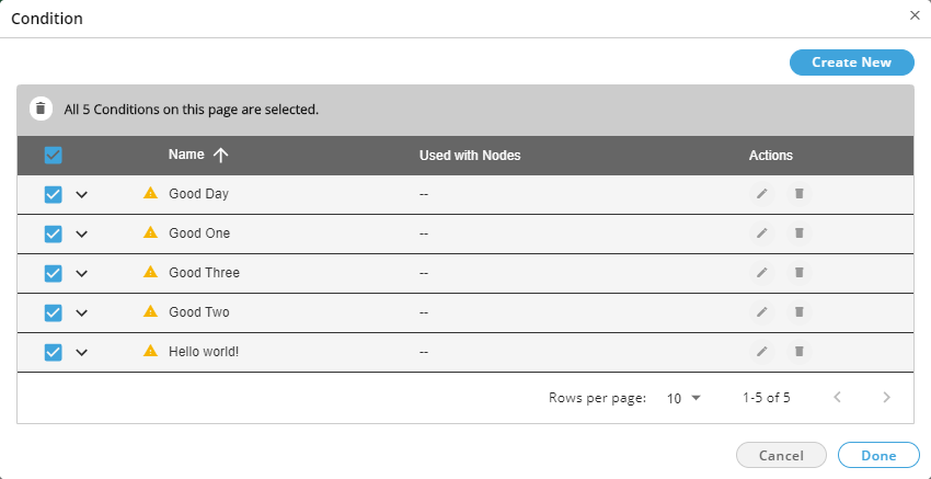
Figure: Selecting all Conditions
The header now shows the option to delete all conditions collectively. The User can click
 icon to delete the conditions. It shows the following warning message.
Figure: Warning before deleting Conditions
Conditions in Node Properties
"Events" tab of the Properties of a node is also modified. It provides two options: "Create New" or "Select Existing".
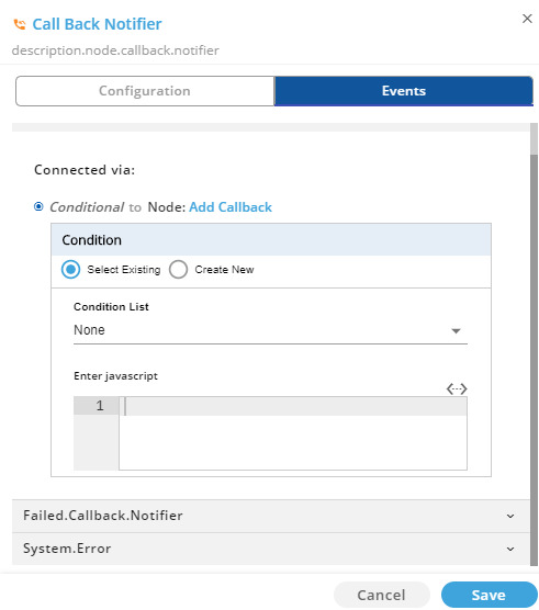
Figure: "Events" Tab of the node properties
The User can select "Select Existing" to select a Condition in "Condition List" drop-down menu.
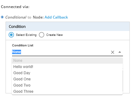
Figure: List of Conditions
The code of the selected condition is displayed in "Enter JavaScript" text area where the user can edit it.
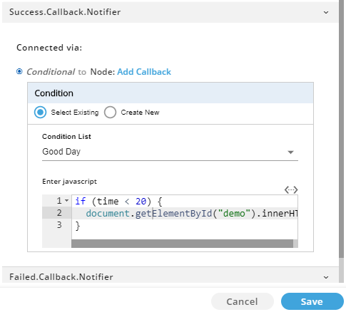
Figure: Selected a Condition
The User can select "Create New" to create a new condition here. This newly created condition will also be available in "Manage Conditions" modal.
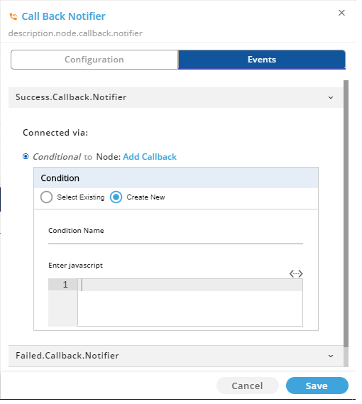
Figure: Create a new Condition
Conditions when the User exports the Nodeflow
When the user exports a nodeflow containing the conditions, all conditions and their links to transitions will also be saved and exported to ".anfx" file. The conditions will be available in "Manage Conditions" section on exporting, if a nodeflow has conditions.